
Making a PCB
This is a little writeup of my experinces with the TVM802A pick-and-place machine from China.
Pick-and-place is one part in the process of creating a working electronic circuit boards. Electronic circuits schematics are created on a PC, then converted into a PCB layout. PCBs are then fabricated by etching and printing.
To create a working board, solder paste is placed on the board using a stencil. Next, all components are picked from reels and placed on the PCB. Finally, the PCB is placed in an oven where the solder paste melts and connects the components to the pads on the board.
Connectors and some components are often soldered on manually. After that, the PCB is finished and should be ready for action.
TVM802A

The TVM802A is the cheapest PnP machine on the market that features dual cameras. The cameras are used to find the exact position of the PCB (downfacing camera on PnP head) and to align the components after they were picked (upfacing camera at the bottom left of the work area), so they are placed correctly.
I am currently planning 60 small PCBs that control the electromechanical display in a gas pump. Placing all the components on the board is tedious and error prone. When I saw the machine online, I decided to order one.
Ordering from China

Ordering from China is always – um – interesting. All prices are negotiable. Communications is via WhatsApp, SMS, or EMail, maybe online chat. You have to advance the money, and shipping costs are shocking.
Depending on your destination address, you need to add import tax and VAT. And even shipping via air freight can easily take four weeks. And when your crate finally arrives, customs may ask you silly questions before the machine is actually released (in Germany, add 10% tax to goods and freight., then add another 19% to the sum).
So I ordered June 22nd, 2015. I paid via PayPal (which took seconds vs. my bank, which takes weeks, but adds another 5% on you tab), and my sales contact promised to ship on June 23rd.
First Impressions
The machine was shipped immediatly (Payments via PayPal was confirmed within seconds, shipping happened the next day. arrivel in Germany three days later by DHL). Delivery was delayed by customs because DHL tried to reach me via some address they found on the internet. I am unsure if the sender missed adding my contact information, or if DHL got confused. 12 days wasted.
As far as I can tell, the shipment is complete. The crate was padded very well with foam. The machine is clean and sturdy. All vacuum nozzles are here, CD is here, wires are here. I am impressed. Only the power cord is Chinese, but should I really complain about a 2 Euro power cord?
The software is translated well enough. I saw one or two fields with a missing translation. But I was able to understand easily what is going on. The manuals are semi-automatic translations from Chinese and sometimes hard to decipher. Good enough. The machine comes with video clips on the CD that are helpful, once you have actually used the software.
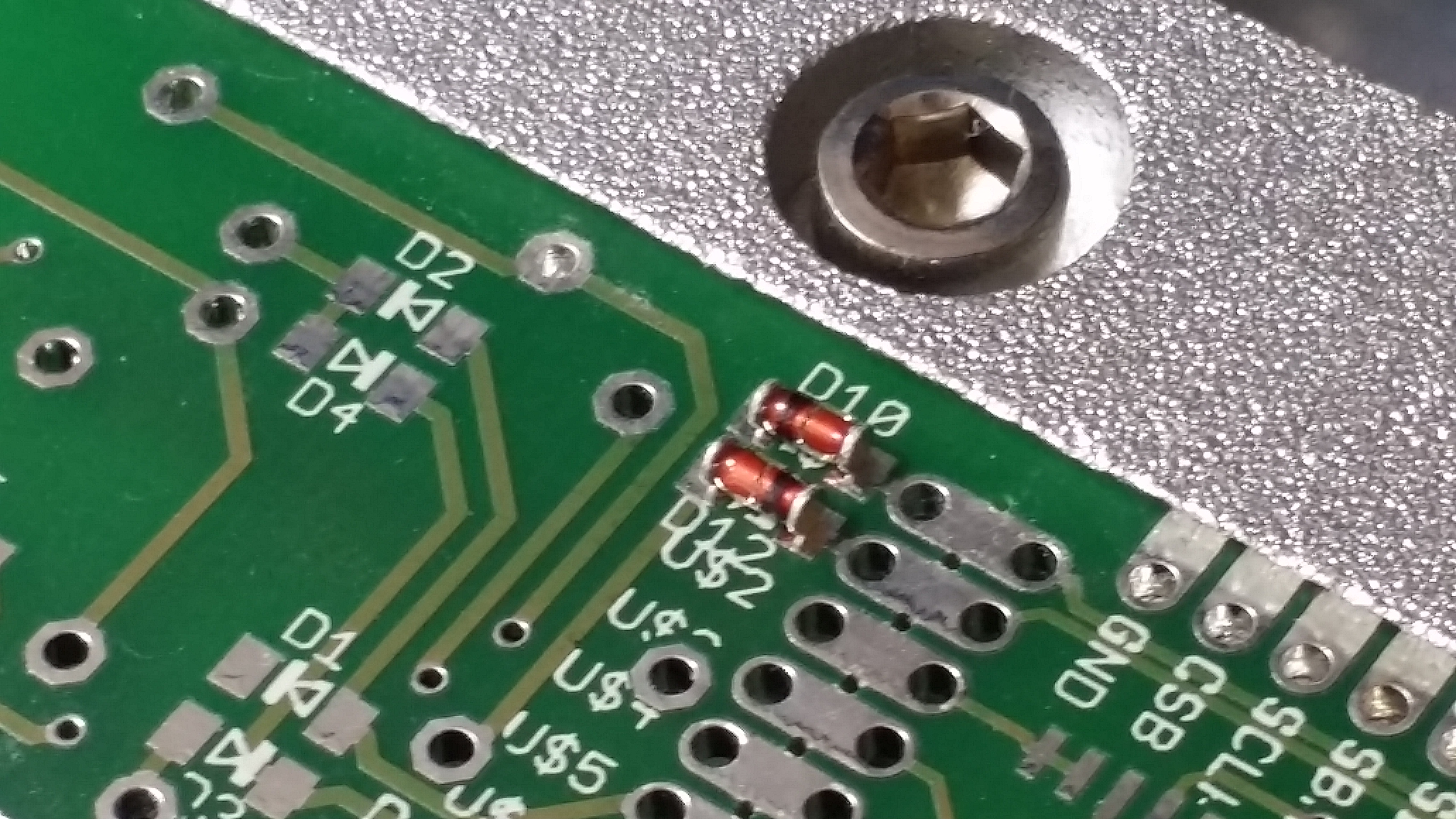
Reading through the manual, it says that Win8 will not work, XP may or may not work, and Win7 is recommended. Well, I just bought an XP laptop becuase many drivers never made it to Win7 and up. It turns aout that Windows 8 works great. I havn’t even tried Windows 7, and XP fails due to the lack of drivers (which is interesting as the cameras used are from Microsoft. Go figure).
The software is quite clear and pretty easy to follow. It’s logical (as opposed to my laser cutter software), and it seems to be complete. The .CSV format is wonderfully simple. Adapting an Eagle ULP should be easy.
A Second Look
So today I was able to start and test the machine. The software works fine on Windows 8, but it will not work on XP SP3. The cameras in the machine are Microsoft Xbox 360 Live Vision Cameras which do not work properly with SP3. They are supposed to work with SP2, but I did not try that and downgrading is not an option.
On WIndows 8, both cameras are found without the need to install a driver. Both USB cables must be plugged in via USB 2 ports or better. The machine itself uses an Ethernet connection with a fixed IP. The software can be used as-is right from the CD. There is no installer. It’s 99.9% English and relatively obvious to use.
Unfortunatley, the application windows are quite huge to make room for Chinese lettering and don’t fit onto my laptop screen. I have to see if there is some way to scale things down. Running the TVM802A from a subnotebook is not possible. The controls would simply not be visible on a small screen. Running the TVM802A from a subnotebook is not possible. The controls would simply not be visible on a small screen.
The microcontroller in the machine seems to be limited. None of the controls work without the host software up and running. There is no SD Card slot and no standalone operation. All operations, all controls, all image processing is done on the host machine, requiring two USB and one Ethernet connection at all times. It’s a design decision and it makes sense. Using the machine without vision would be a waste, and adding a vision system to the machine would have made it more expensive. I dedicated an older laptop to the machine and that should be just fine.
Testing all Functionality
In manual mode, all degrees of freedom can be tested. That would be X and Y axis motion, transport pin up/down, pick’n’place head 1 and 2 rotation, lift, vacuum, and and blow, and not to forget the protective film collector. Then there are the camers, the lighting, and the buttons. Everything works well.
The Host Software (V2.0)
I did manage to program the picking and placing of some parts. Calibrartion data is stored in the machine and is retrieved and used by the host software. Creating a pick’n’place program manually is quite painful and nothing you would do on a regualr base. The cameras have quite some lag. Make sure that the right camera is assigned to the right interface, or nothing will work as it should.
But I should not complain: nobody in their right mind will do this manually. Every PCB design software has a way to export pick’n’place data.
But enough for today. It’s the weekend. I will continue Monday, shooting some pictures and maybe a video.
Happy hacking!
ToDo:
- export current PCB from Eagle
- test-place all parts
- fully place a PCB
- solder and test 😉
Unboxing
Sturdy construction
The Stack and the pick up area
Simple, but working well.
One of my PCBs and two automatically place Rectifiers
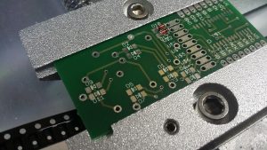
It took me a while to figure out why the rectifiers were misaligned. When new nozzles are installed, the software can measure the nozzle position for various rotations, compensating for a slightly bent nozzle. My “Nozzle Threshold” was set too low (was 45, now 85), and the software would not recognize the nozzle hole. After correcting this, the left nozzle places the parts perfectly. The right nozzle places with a healthy offset – still figuring it out. Also, please see the Sun Visor Mod further down on this page.
Much better Alignment
After setting the correct nozzle threshold, the diodes are placed nicely.
Setup
TVM802 and Windows 8 setup
The Windows Host Machine
The TVM requires three data connections to a host PC. I highly suggest a dedicated machine to control the TVM. I bought a relatively simple laptop with three USB ports, Ethernet, and Window 8. Windows 10 should work just as well.
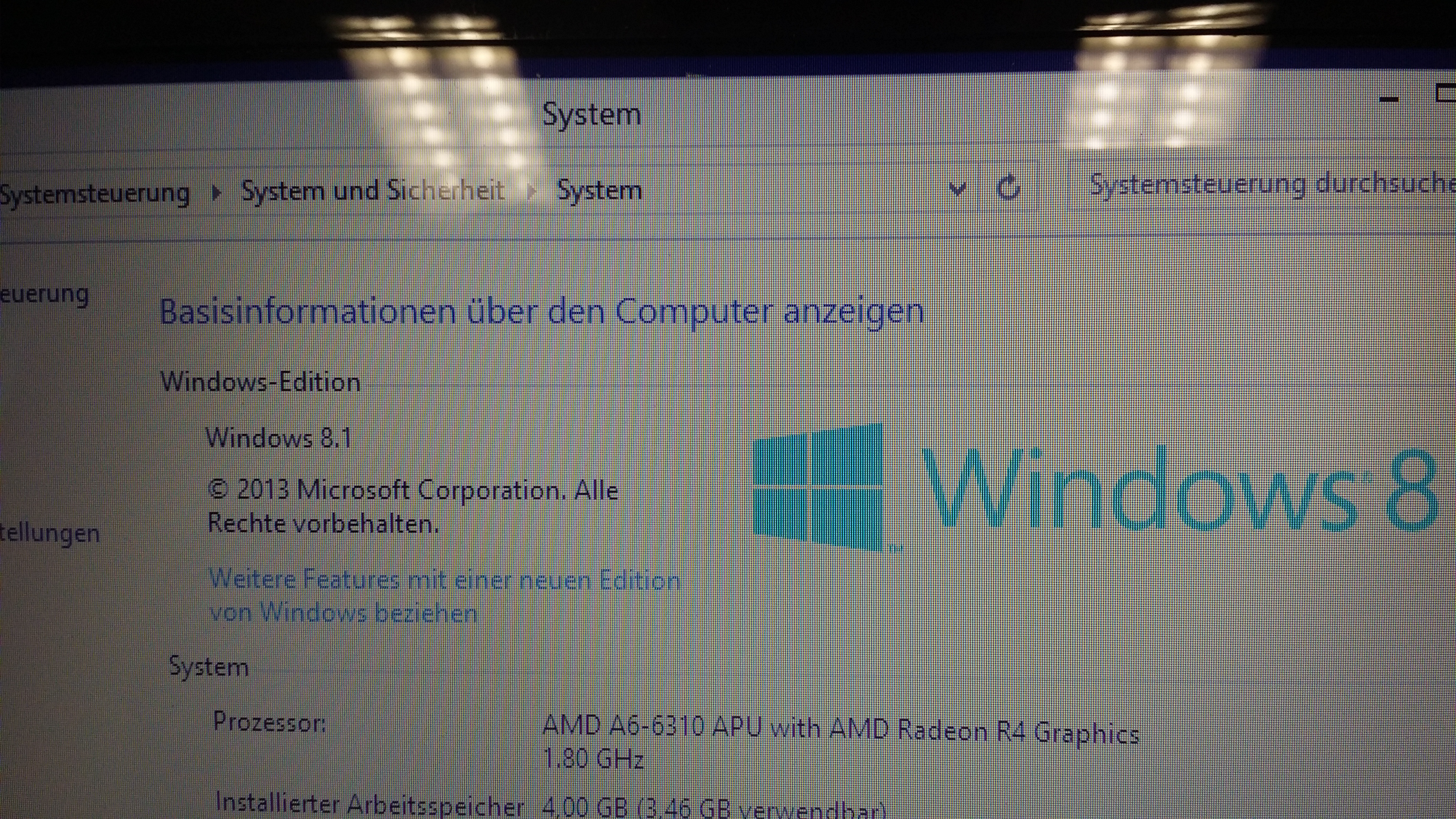
The basic Wiring
The TVM comes with three data ports that must be connected to the PC. The machine commuinication runs through an etherent connection. It’s easiest to get a crossed ethernet cabel and connect the TVM directly to the PC. Don;t put the machine on your shop network. It’s not worth the hassle. If you want tp make sure that the machine is sending and receiving data, get a cheap dumb ethernet router that has LEDs and two ethernet cables that are not crossed. Don’t use a smart hub or modem that puts additional DHCP traffic on the connection.
The ethernet port is set to the fixed IP 192.168.0.8 and port 701. You can’t change these settings until you successfully connect to the machine!
USB Wiring
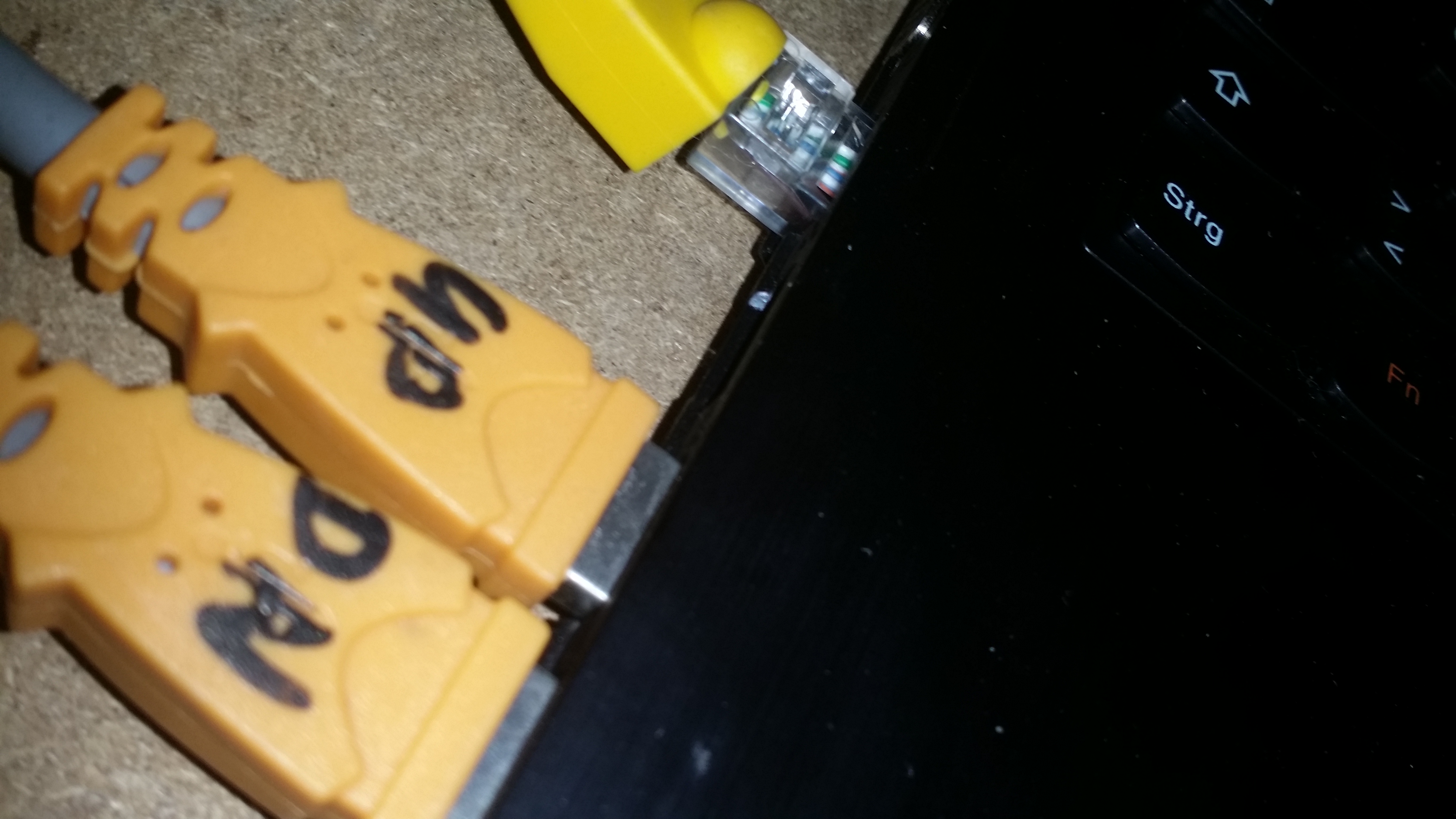
Next to the ethernet connection are two USB connections that hook the cameras to the PC. The picker does not use any of the image data internally. All image processing is done on the host computer. Connect the cameras directly to the computer. Do not use a USB hub!
The cameras are Microsoft XBox cameras. Don;t use the driver that comes with the machine. WIndows 8 and10 should recognize your cameras instantly. Make sure that they show up in the hardware manager, and use any video viewer to verify that the cameras are delivering images.
How To Hook Up Ethernet

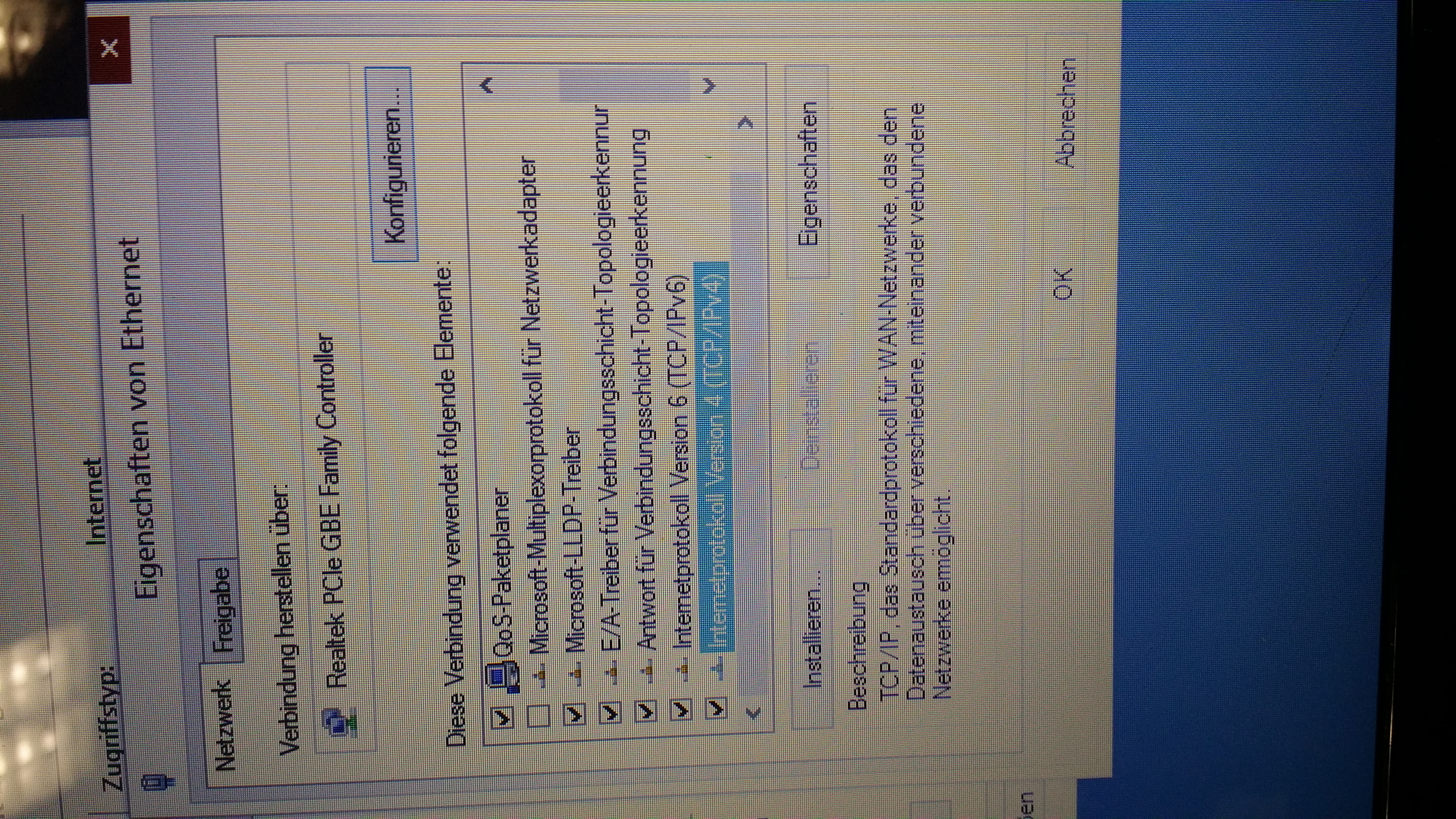
The ethernet connection has become somewhat of an issue for some users. A fixed IP is relatively uncommon in office networks. So here is how you do it. Assuming that the machine is hooked to the PC as described above, open your network settings. Go into Ethernet Propertis, then select TCP/IPv4 and open the dialog.
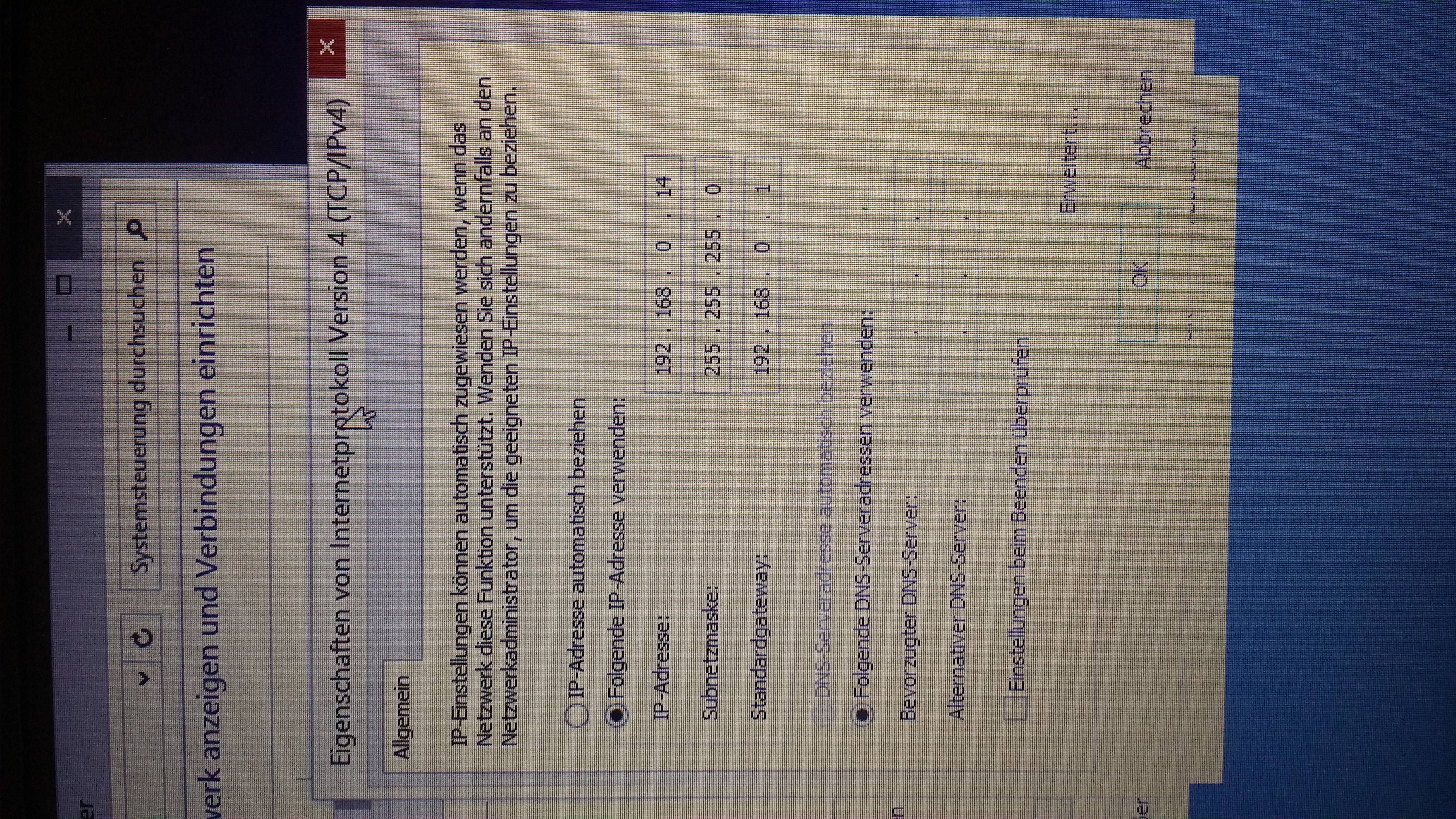
Set the first choise to use a fixed IP and enter 192.168.0.14. The second line is the subnet mask. Set it to 255.255.255.0. The standard gateway is ignored, but set it to the standard 192.168.0.1. The DNS entries should be set manually to, but the field must be left empty.
Launch Surfacemount.exe
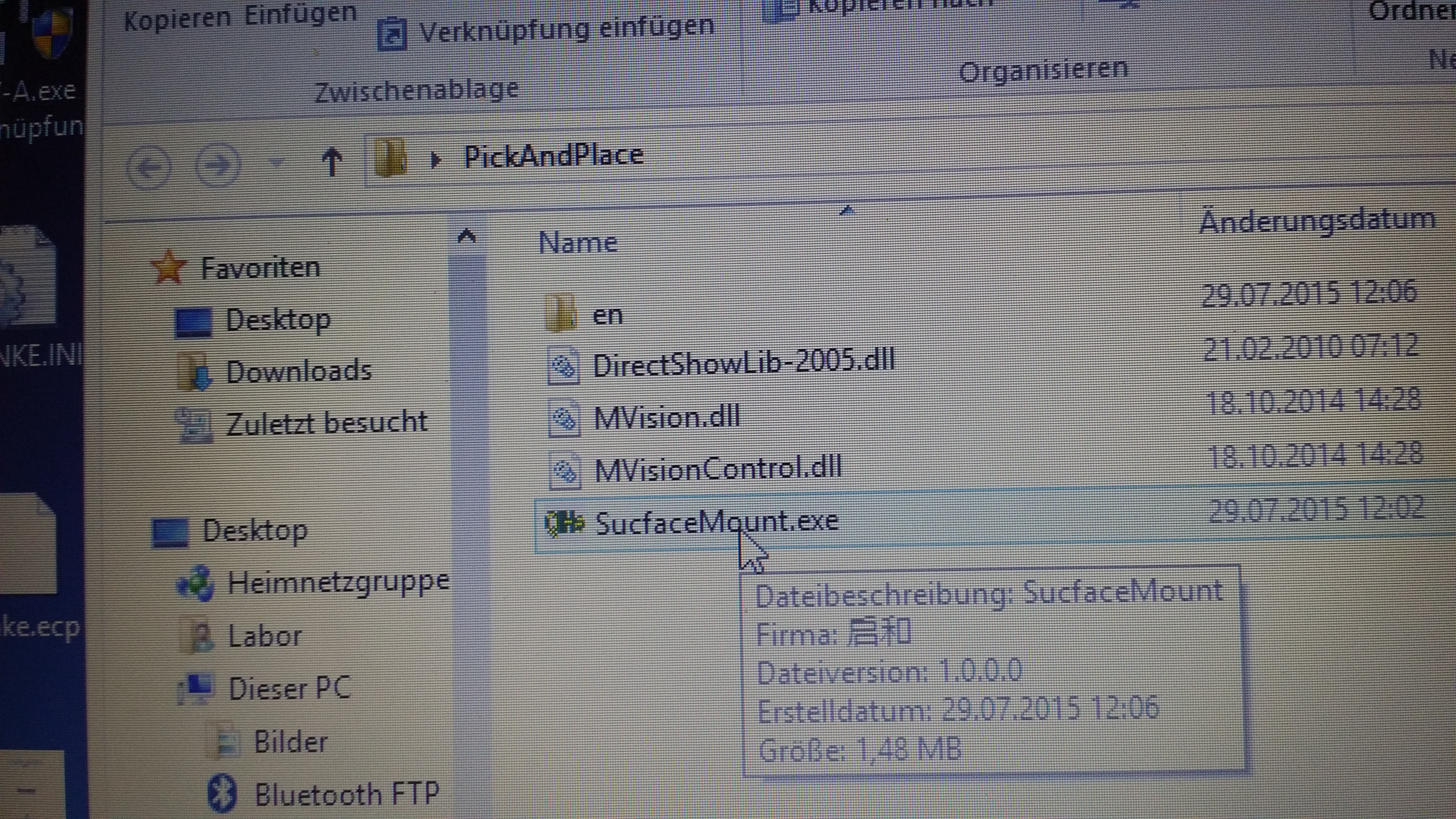
Launch the software that came with the TVM. It may take a minute or two, but eventually, you should see the Load page, containing a table view on the left and a camera view at the top right.
If you get an ethernet timeout instead, go through all the fixed IP ethernet settongs again. swap cables, add a router, check for blinking LEDs. Still not working? Ask a network administrator to help you with the network setup (avoid having a wireless network running on the same machine). Check if there are other ethernet port on your machine.
Moving About
When the ethernet works, change to the Move window and try out all the motors. At the bottom right, there is a panel that can step through every conceivable motion. If there is another panel, clivk Moveagain. If everything work, it’s time to send the machine home – oops – sent the pick-and-place head to its home position. Click on Home and Run‘ The head should position itself at the back right corner of the machine.
Testing Camera Settings
Use the Move commands to send the head all over the machine. Get familiar with the chinese logic of naming and positioning user interface elements. When you are done, ttake a look at the camera window. Double-clicking the window cycles between up facing camera view 1: nozzle alignment, upfacing camera view 2: chip alignment, and downfacing caera view 3: PCB marker search. Make sure that the up and down facing views are assigned correctly. If not, fix it in the settings by changing the ca,era ID.
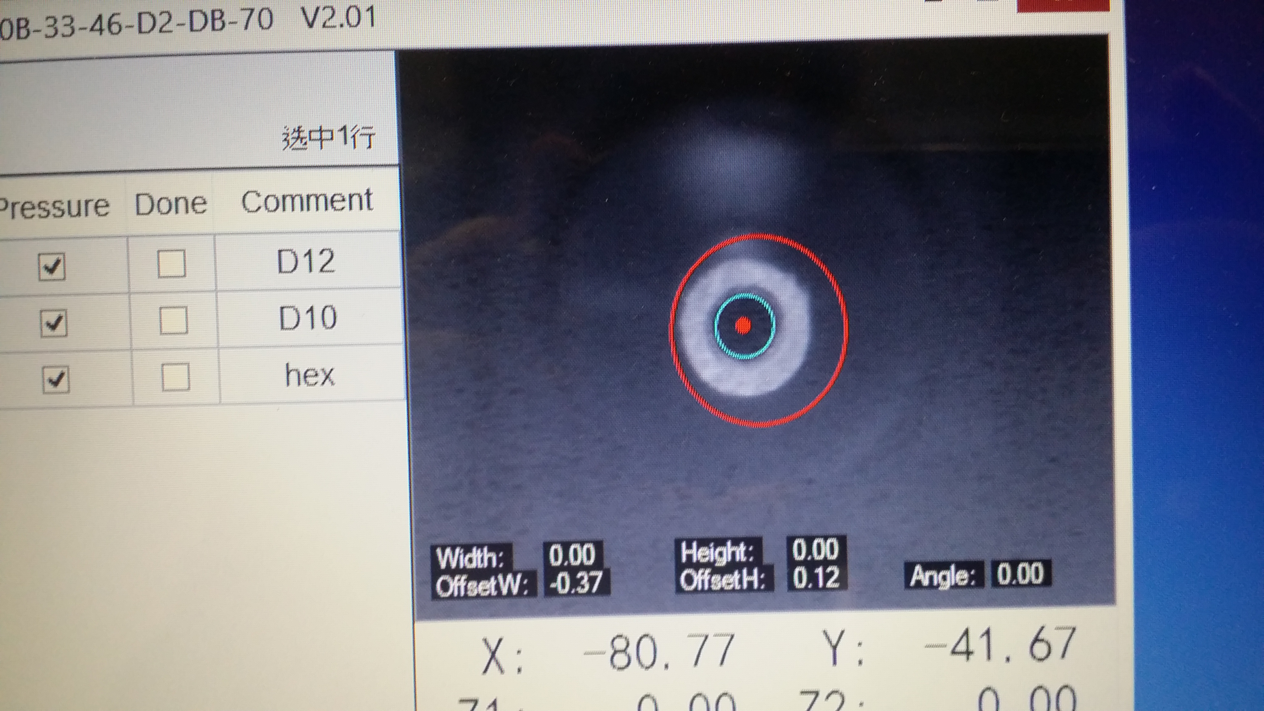
Nozzle alignement with upfacing camera.
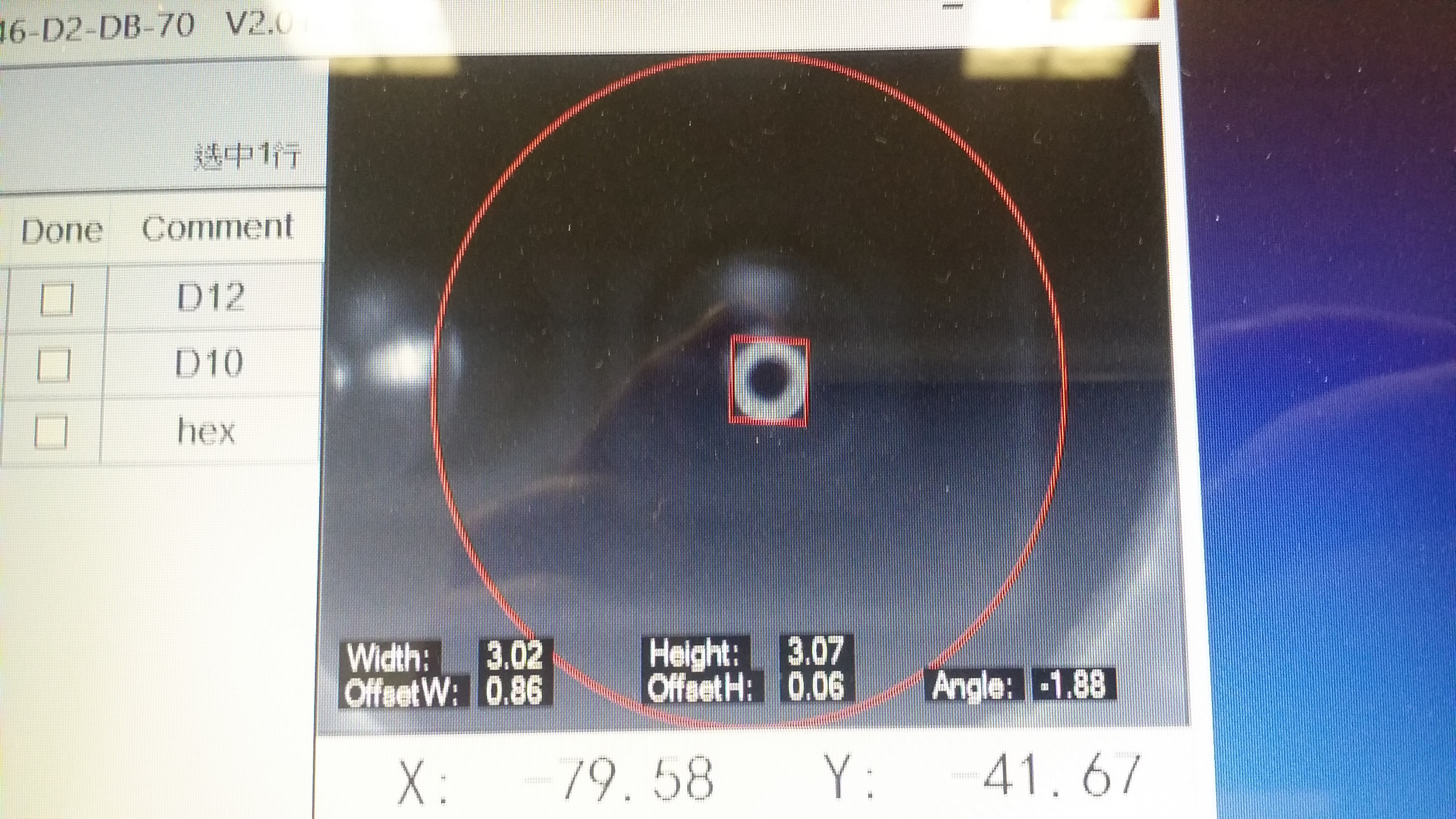
Chip alignment with upfacing camera. Note the difference in the graphics.
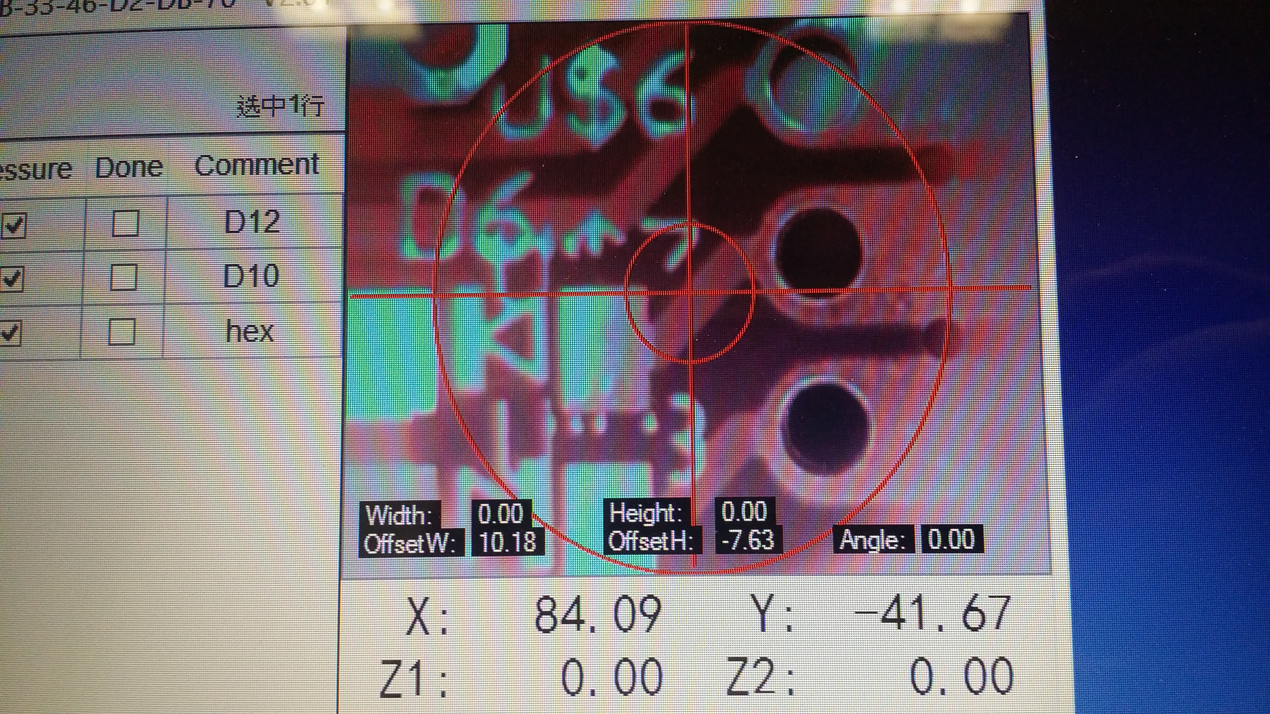
Downfacing PCB algnment. Yes, the colors are funky, but it still finds the markers.
Well, I hope that everything works for you so far. The pumps are pumping, the index pin is pinning, the nozzles are rotating and lifting, and the carriage is carrying.
Sorry for the bad photos and the German text. I hope that this still helps.
First PCB
Mods
Sun Visor
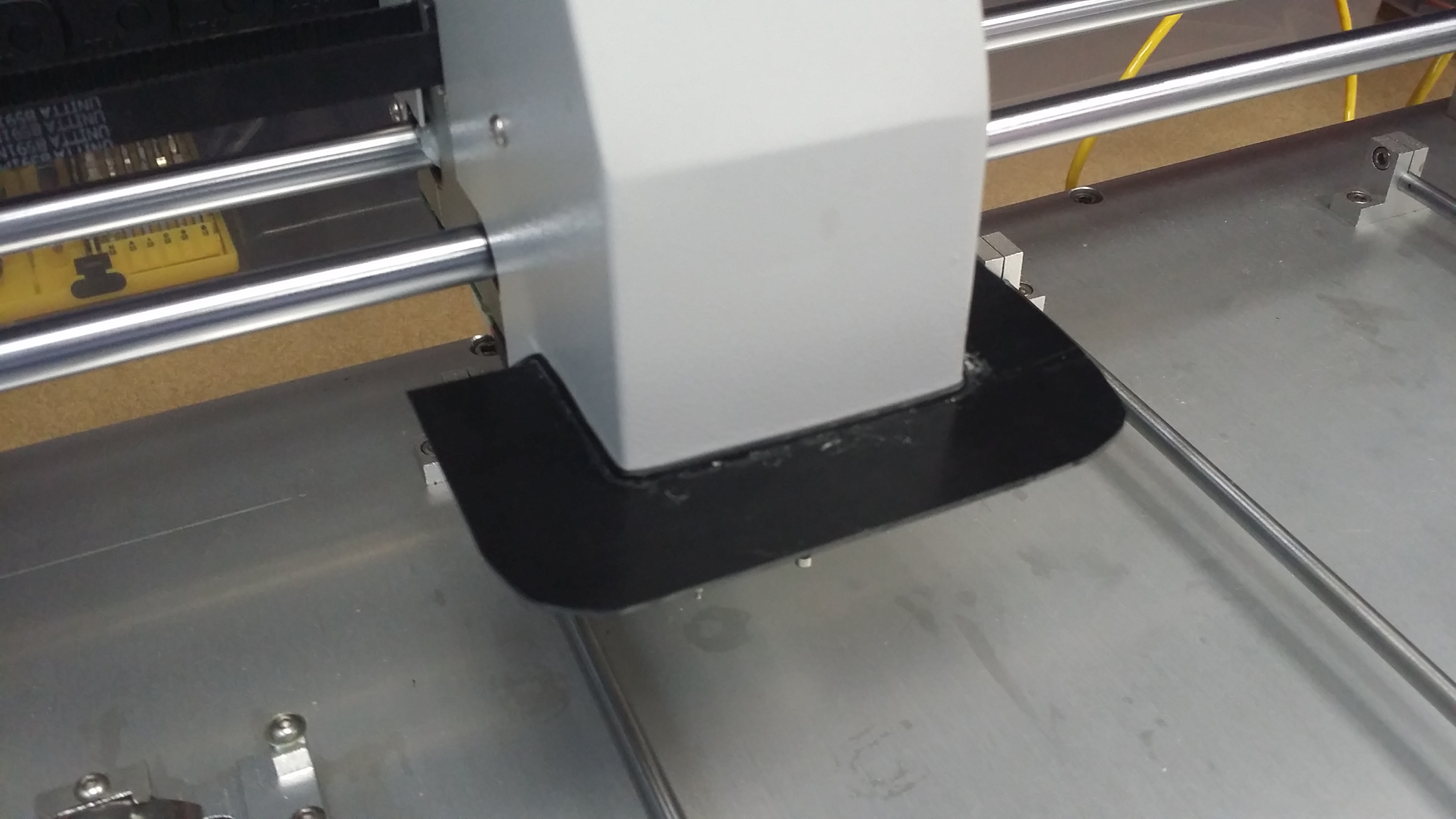
When the lower camera looks up into the nozzl tip, the sides of the camera image pick up parts of the room’s ceiling. This is particularly bad if there happens to be a fluorecent ceiling light. It will keep the machine from recognizing the nozzle tip and from aligning correctly.
A simple sun visor from black plastic, glued on with crazy glue, resolved the issue in seconds. Yay!
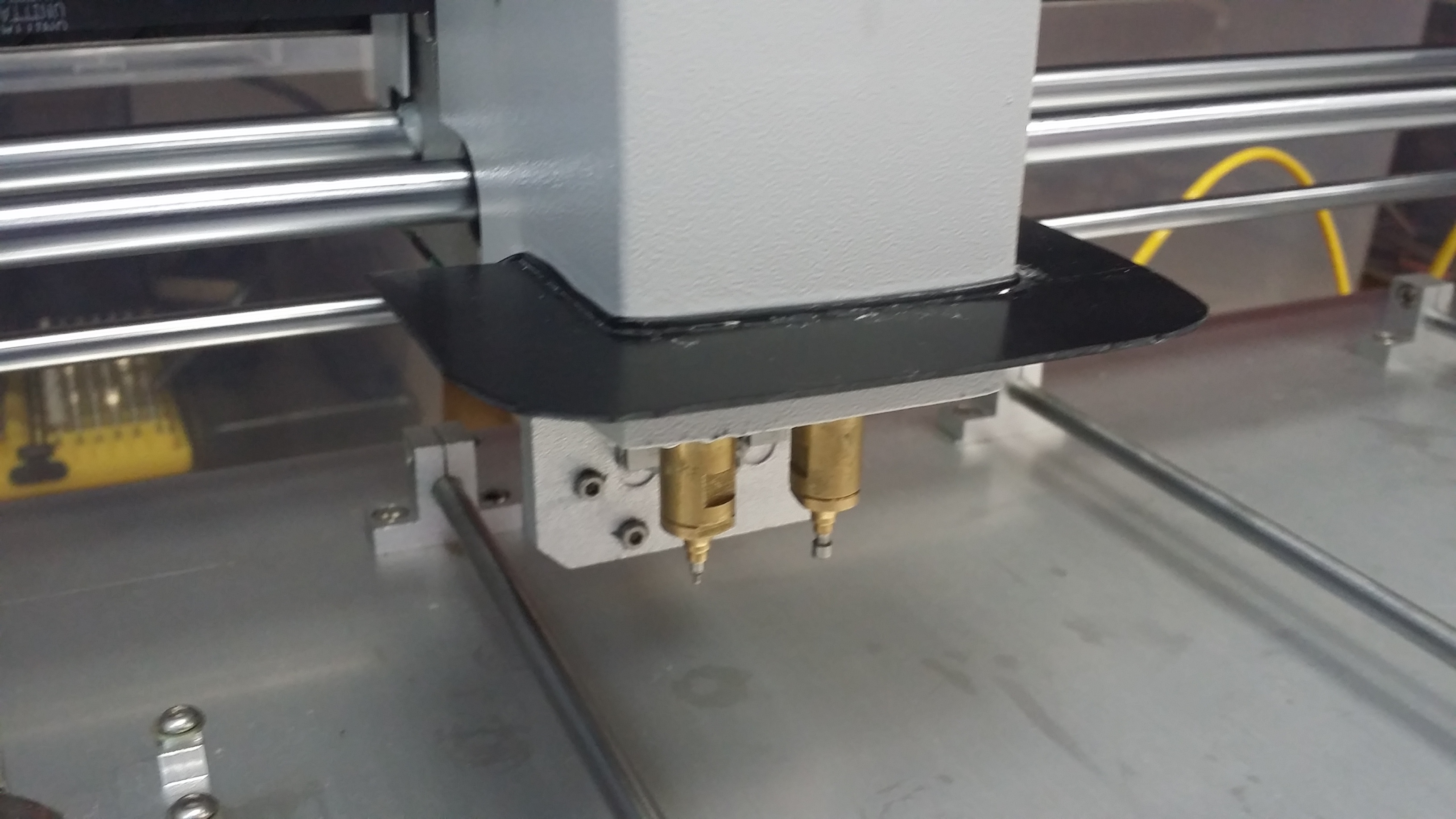
The little line between the visor and the case is a piece of black wire, for optics and stability.
Hacks
Overview
Connections:
- Power
- USB Camera 1 (cameras are directly connected to host PC and not recognized by machine, camera lighting may run via USB or separate channel)
- USB Camera 2
- Ethernet with fixed IP (TCP/IP connection)
Actors:
- X Stepper Motor
- Y Stepper Motor
- Suction Pump
- Suction Relays 1 and 2
- Pressure Relays 1 and 2
- Vaccum Tip lift 1 and 2
- Tip Rotation
- Transport Plunger
- Reel Waste Transport
- Camera LEDs
- Status LEDs
Sensors:
- X Endpoints (left, right)
- Y Endpoints (left, right)
- Vacuum tip top (1 and 2)
- ?? Vaccum tip 0 angle (1 and 2)
- Suction (1 and 2)
- Plunger top
- Push buttons (7)
- Cameras (facing up, facing down)
Camera Protocol
The camera report as XBOX Vision Cameras to the system. Both Win8 and OS X 10 recognize the cameras without installing a driver. Great!
Ethernet Protocol
The Ethernet connection is TCP/IP. All numbers are in LSB/Intel format (not in network order!).
A status request is sent from the host every 20ms (word 0). The machine replies with a status report, probably for every sensor in the machine. So far, I found the X and Y endstop bits and the bits for the pushbuttons.
Every 200ms, the machine sends a register request (command 1 and the address of some register) which is answered by tha machine with the status of the give register.
When the software establishes a first connection, some 400 registers are pulled form the machine. The use of those registers is so far unknown. I am sure it will contain all the calibrartion data found in the software settings.
Conclusion
The controller in the machine seems to be quite limited. Is has no card reader or any other intelligence. I assume that it is limited to interpreting commands and sending status reports. The commands will include simple on/off requests for motors, relays, and lights, as well as positioning commands for the stepper motors (X, Y, Tip1/2, Tip rotation, Waste).
Creating a clone of the software that comes with the machine should be quite easy. The resulting software could be improved in usabilty and import functionality. And it could work on Apple OS X.
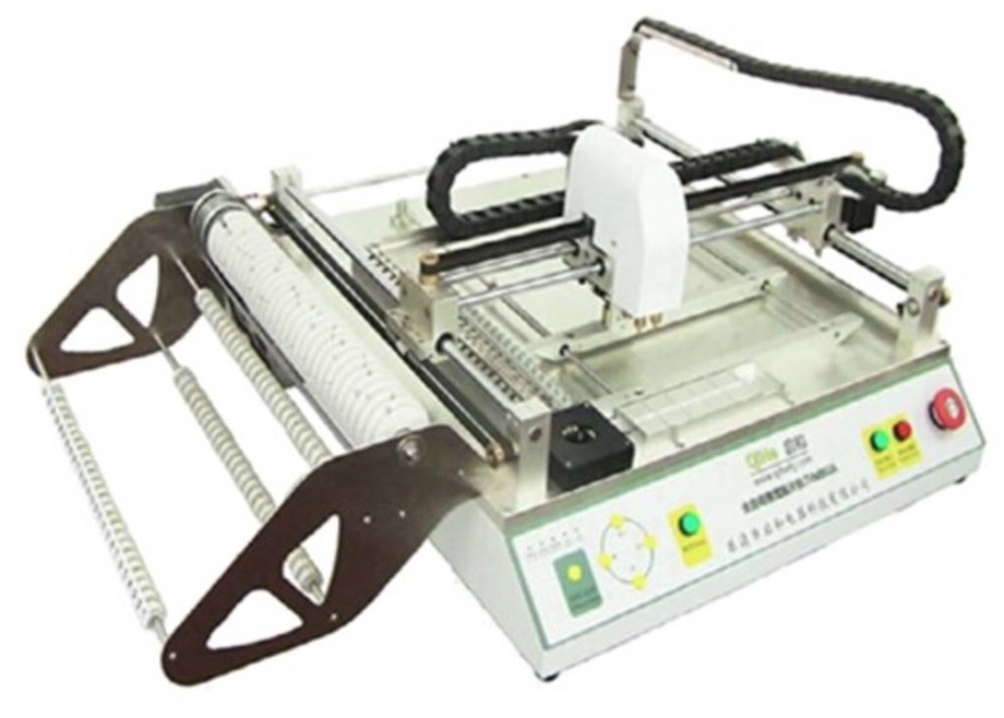
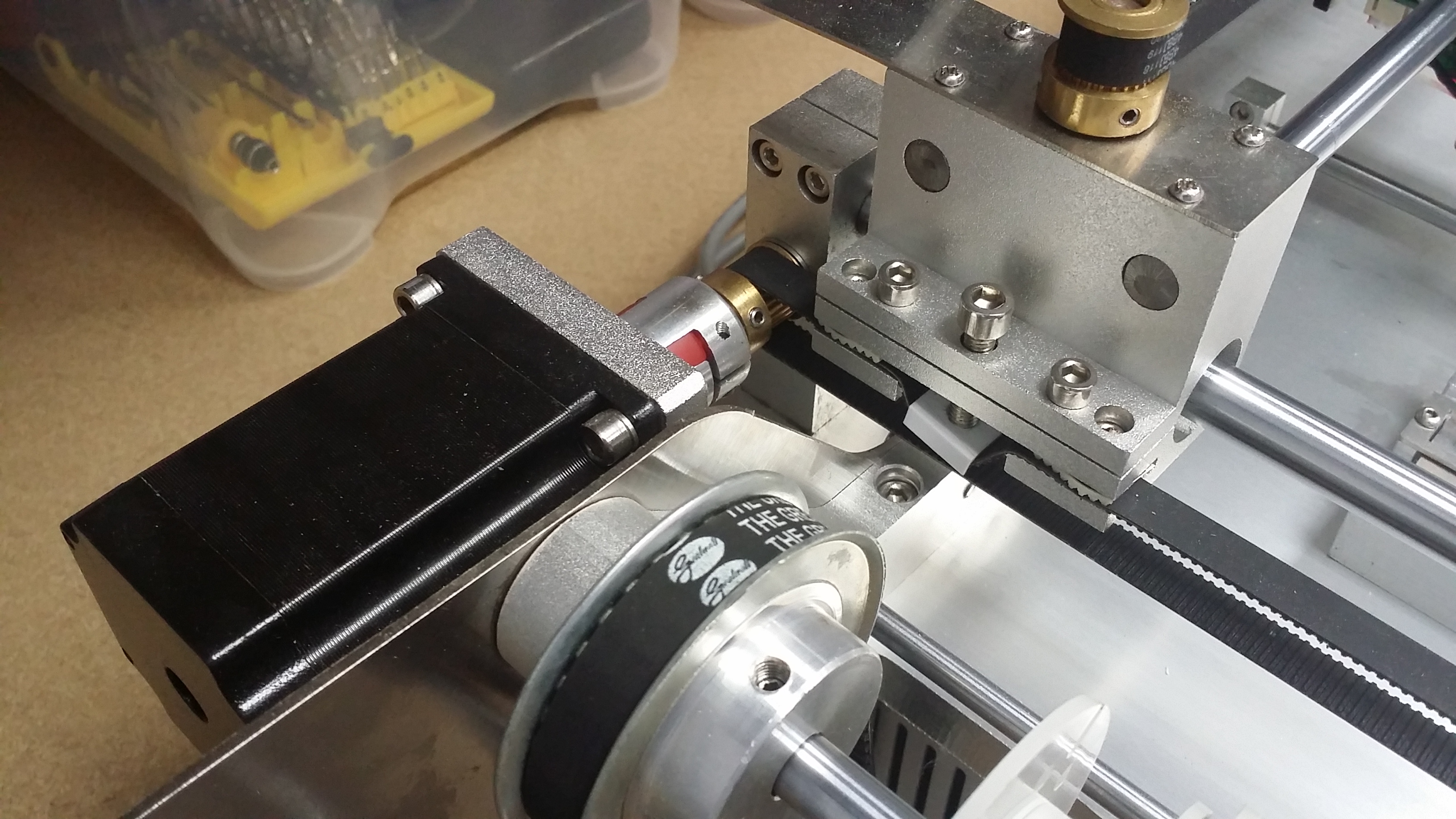
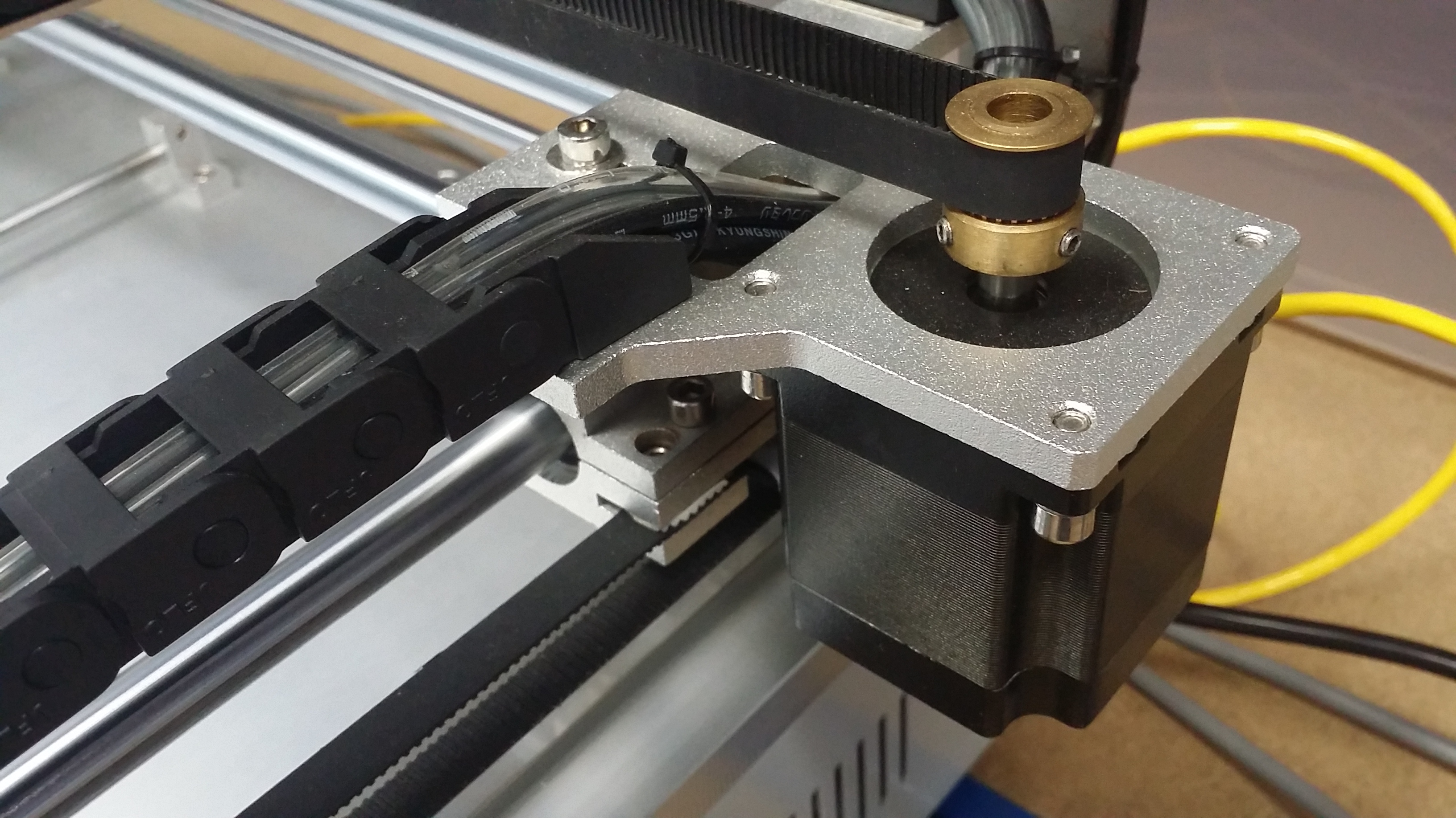
How the Feeder transport works

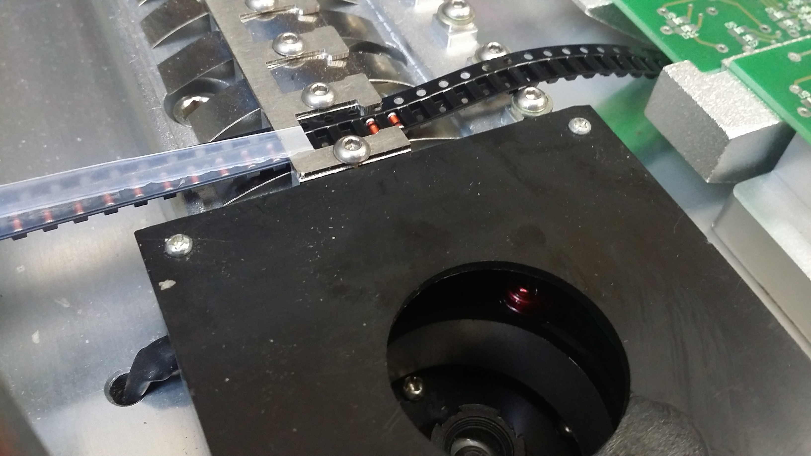
Most SMT components come in rolls. The rolls have a plastic strip with little indentations for the part. A thin film covers the strip to keep the parts from falling out.
The TVM802A holds a stack of 24(?) rolls. The strip passes trough a metal clamp and spring. The picker nozzle uses a vacuum to pick the part from the dip in the strip. If picking fails (the vaccum switch is not triggeres), the part the head moves to a waste bin, then returns to the feeder to try to pick the next part.
To advance to the next part, a plunger (a little steel rod) is mounted to coil (the yellow cylinder in the photo) on the p’n’p head. The head moves to the index hole in strip, then the magnet pulls the plunger down into the index hole. Next, the head moves a few milimeters to the right, advancing the strip. Then, the magnet lets go of the plunger and a spring pulls the plunger upwards and out of the way. Finally, a smaller plastic wheel turns and peels back the thin film on the strip, giving access to the next SMD in the strip. This all happens in a fraction of a second.
The plunge has a sensor that i triggered if the plunger does not return to its top position. This happens if there is too much tension on the strip, and moving the gead would create a huge mess. If it happens, the machine will beep continuously and a dialog box will appear on the host computer.
Eagle ULP
Eagle CAD ULP script file
Creating Pick and Place files from Eagle CAD
I like to use Eage CAD for making my PCBs. The following script generates the required CSV file from the current Eagle Board.
Current version:
mount_tvm.ulp.1.0.1.zip
Older Versions:
mount_tvm.ulp.1.0.zip
Install the ULP somewhere in your Eagle setup, preferably within the ULP user or application library directory. The script will be available immediatly. Switch to Board View and call the ULP with run mount_tvm.ulp.
Features
Current features:
- generate Pick’n’place file for TVM802A
- board rotation
- persistent machine setting
- parts are sorted by value and package type
- stack indexes are incremented automatically
- nozzle and stack are selected by part size
- visual alignment is selected by part type
- persistent board settings
Comming soon:
- support for fiducials
- more machine settings
- multiple boards
- support for bottom layer placement
Even more features:
- stack database, management, and optimization
- part database, height, and correction
Output Tab
The Output Tab contains all settings required to write the Pick’n’place file for a TVM802A machine.
The Board Statistics field gives you some information about the board itself and about the SMD parts on the board. Make sure that the information is correct. The board size is needed to calculate the place position for rotated boards.
The Pick and Place Data File selector allow you to pick a filename for the CSV file that will be generated. The default path and filename saves the file where the board file lives. You can either edit the text field, or click on the [...] button to open a file selector dialog.
The Board Rotation field makes it possible to generate place information for a board that is mounted in a different orientation than it is designed in.
- Apply will write the pick’n’place file, but not close the dialog
- Cancel will not write anything and close the dialog box
- OK will write the file and close the dialog
Machine Tab
The Machine Tab provides settings that are particular for one machine and don’t change for other PCBs. The settings are stored as TVM802A_Machine_Settings.txt in the EPF directory.
The Stop Bar Origin is the position of the bottom left corner of the PCB when mounted on the stop bars and pushed left. Use manual mode in the TVM software to position the down-facing camera on that corner. Then create a part enrtry from vision, and the part position will reflect the exact offset of the PCB.
Press the Save Setting button to save all settings in the machine tab for later use. Changes in the settings are not automatically saved when closing the dialog.
Feedback
Please let me know if you have comments or ideas for new features.